


NOTICE
My involvement with xPL has come to an end. Automation has moved on considerably over the past few years, and it is now possible to buy a stand-alone controller off the shelf for a reasonable price, without having to spend hours writing your own code.
This website is being maintained as a record of my xPL development work up until 2011.
I have released the full source code of all my xPL projects into the public domain. You can download the archive from here.
Mal
Network Diagram
The diagram below illustrates the path of a typical xPL message through the network. Starting with movement detected by a wireless motion sensor, it shows how xPL might be used to turn on a light.
Note that the green and orange lines represent the path that the messages take, and are not the physical network cables.
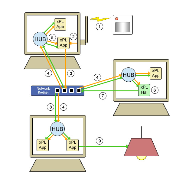
1) Motion sensor detects movement and broadcasts an RF signal.
2) The signal is picked up by the RF interface attached to the PC, and read by the xPL connector application.
3) The xPL connector application broadcasts an xPL trigger message describing the event (orange arrows).
4) The network switch transmits the message to all PCs on the network. This message will be picked up by the xPL Hub running on each machine.
5) Because of the broadcast and hub system, the connector application receives back a copy of the message that it sent.
6) xPLHal receives the message from its local hub.
7) xPLHal decides to respond by broadcasting an xPL command to turn on the light (green arrows).
8) The network switch transmits the command to all the PCs on the network (All xPL applications receive a copy of every message that is sent)
9) The command arrives at the xPL connector application that controls the lights. The light is turned on.
For more detailed information on xPL, schema definitions and links to xPL applications, please visit the xPL Project Wiki.